Hello! I'm Amogh, a postdoctoral researcher in Computational Science Center at the
National Laboratory of the Rockies, renamed this year from the National Renewable
Energy Laboratory (NREL). I build numerical models that tell engineers whether a
reactor will actually work — before anyone spends millions finding out.
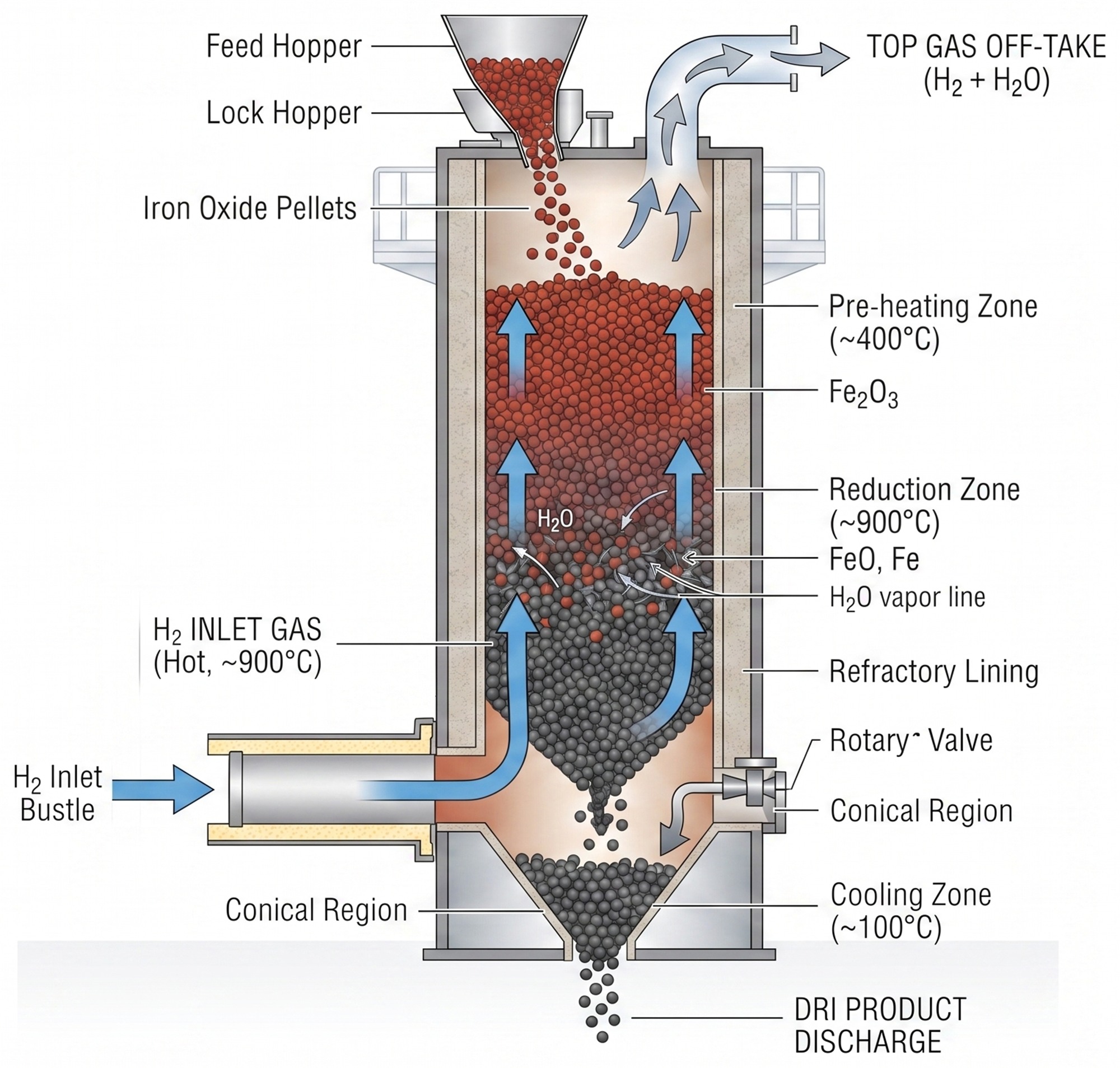
Where I work — the National Laboratory of the Rockies campus in Golden, ColoradoThe reactor I model — Direct Reduction Reactor for Ironmaking using H2 and Natural Gas
Right now I make 3D CFD-DEM models of iron ore reduction in Ansys Rocky, running
on HPC and resolving individual pellets, the gas moving around them, and the chemistry
happening inside them. Alongside that I'm building a single-pellet model in AMReX to
scale up from — and I've automated much of the modeling pipeline with AI, so more of
my time goes into physics and less into plumbing.
The PhD Years
My PhD research at Arizona State University was done as a part of the GISH project under the supervision of Prof. Sridhar Seetharaman.
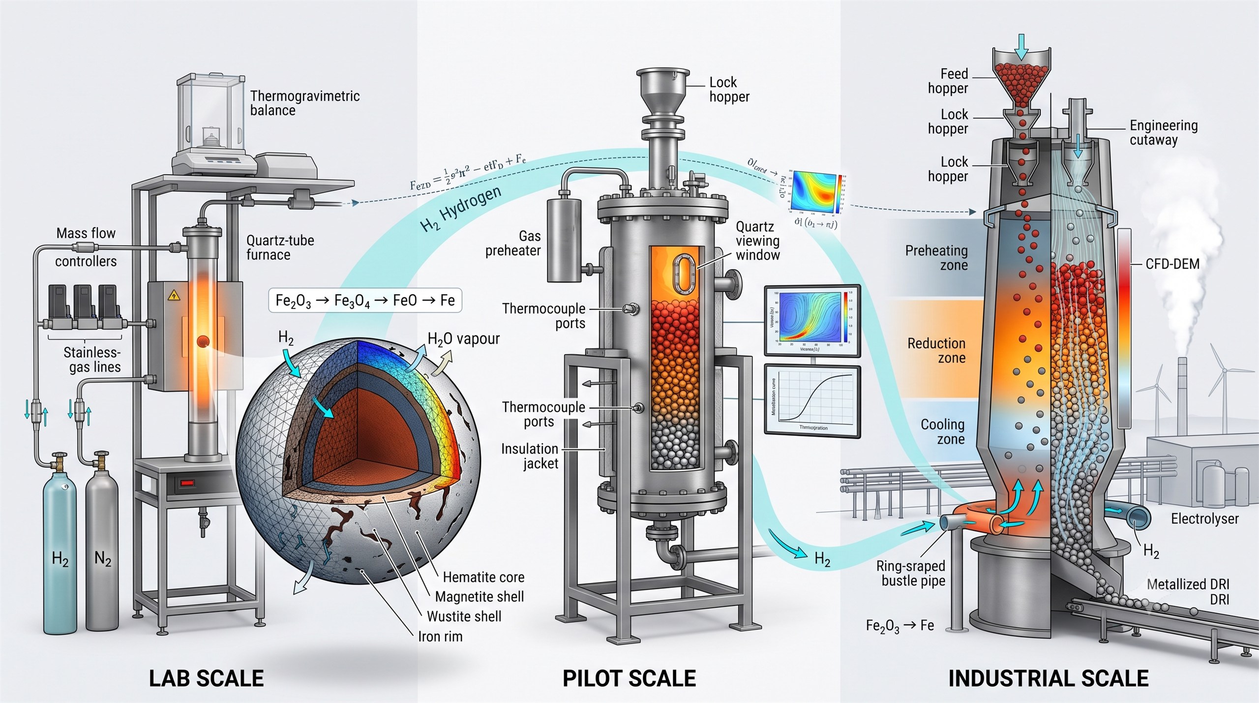
My thesis was titled "Modeling and Simulation of iron ore reduction
at lab scale, pilot scale, and industrial scale". What changes across those scales
isn't the physics and chemistry — it's which simplifications you're still allowed to make.
The thesis in one picture — the same reduction chemistry carried from a single pellet, to the pilot reactor, to an industrial shaft furnace
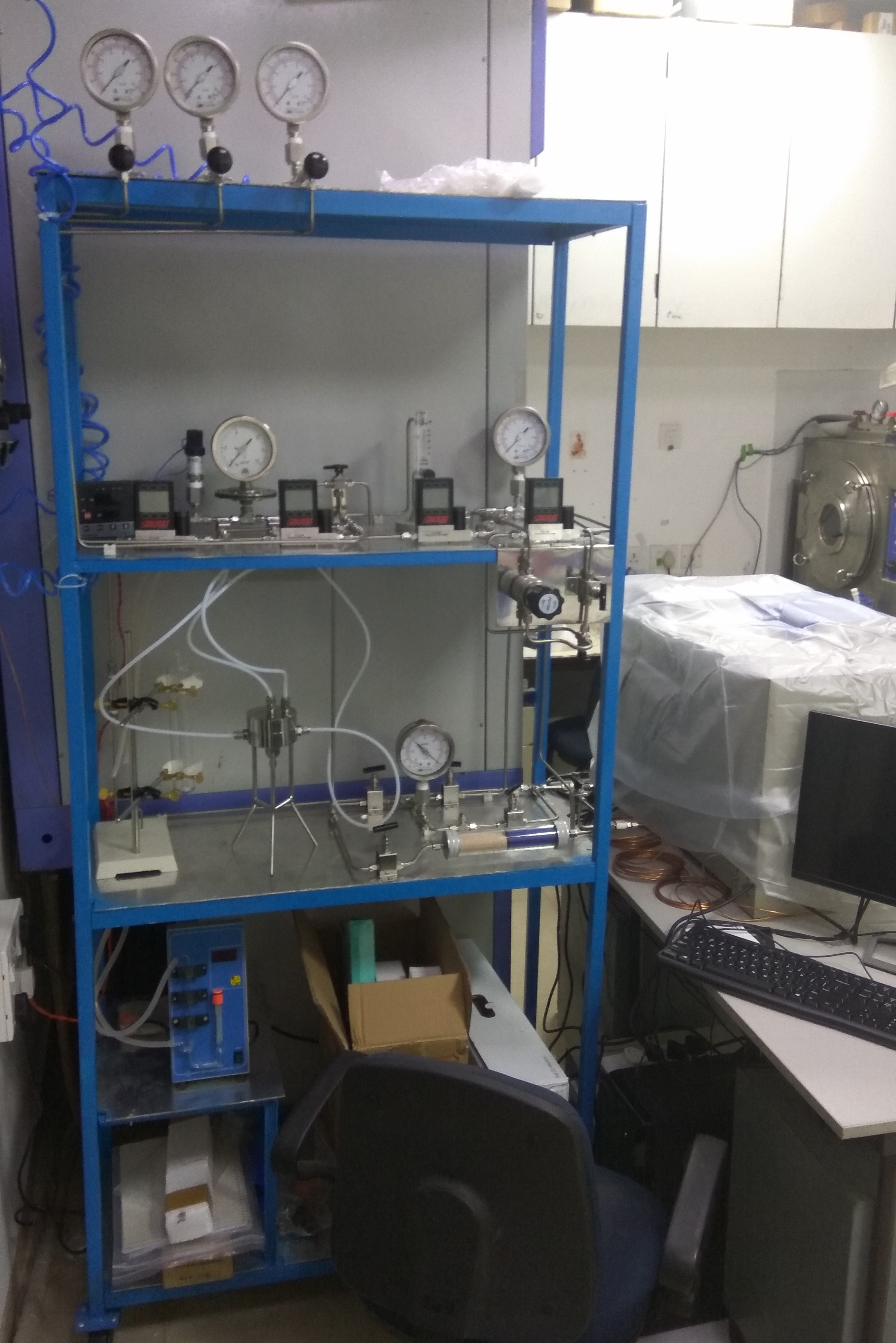
I ran the experiments that fed the models too, building a gas mixing rig and characterizing
pellets with FE-SEM, TGA, and porosity analysis. The project commissioned the first
pilot-scale reactor capable of reducing iron ore pellets with both hydrogen and natural
gas, which is where I learned what simulation can't teach you: what fails first, and which
of your assumptions were load-bearing.
Where It Started
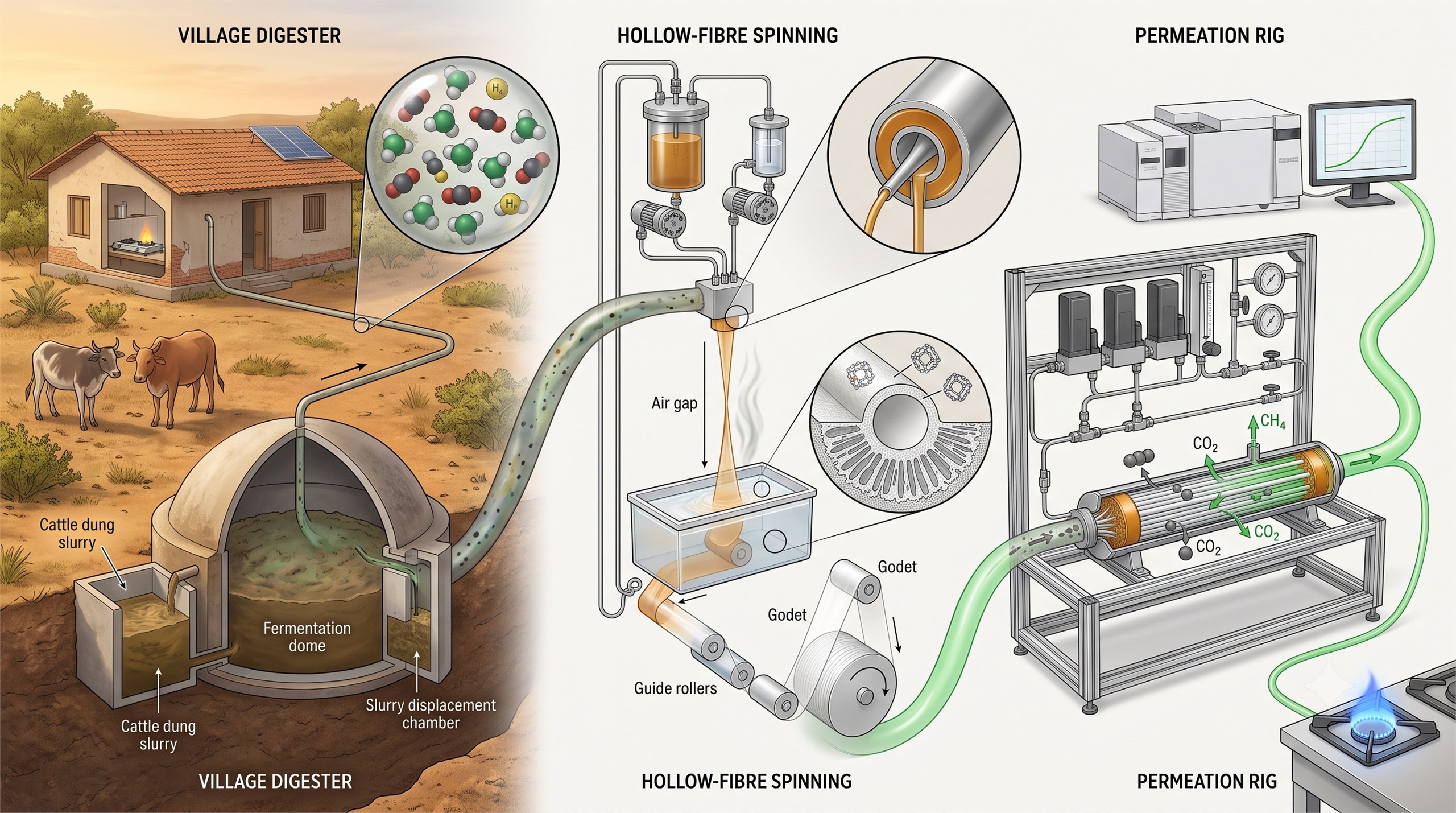
Earlier I spent two years on gas separation membranes and electrospun fibers, building
both a separation rig and an electrospinning setup from scratch. That started at IIT
Bombay with dual degree work on biogas purification, where I also spent time in rural
Maharashtra studying how biogas actually gets used — the clearest lesson I've had that
a technology only counts once it survives the field.
Where it started — village biogas, then hollow-fibre membranes built and tested to clean it up
The software and instruments I actually work in, day to day.
COMSOL Multiphysics
Coupled flow, heat, mass transfer and kinetics
Ansys Fluent
Computational fluid dynamics
Ansys Rocky
Discrete element method, coupled CFD-DEM
AMReX
Block-structured adaptive mesh refinement
OpenFOAM
Open-source CFD toolbox
C++
Custom solvers and post-processing
Python
Scripting, data analysis and automation
Agentic Modeling
AI agents that set up, run and post-process cases
Agentic Workflow
Automated pipelines from setup to report
FE-SEM & EDAX
Microstructure and elemental mapping
TGA
Reduction kinetics from mass loss
Six Sigma Green Belt
Lean, DMAIC, OpEx, root cause analysis
Expertise
What I get hired to do.
01
Multiphysics Modeling & Simulation
Finite element and discrete element models that solve fluid flow, heat and mass
transfer, and reaction kinetics as one coupled system. Built for equipment that has
to work in the real world, not just converge.
02
Agentic AI & Workflow Automation
AI agents that build cases, launch them, post-process the output and draft the report —
the plumbing around a simulation rather than the physics inside it. The point is to
spend engineering time on judgement rather than on shepherding files.
03
Scale-Up: Lab to Pilot to Industrial
Carrying kinetics measured on a bench sample all the way to full-size equipment with
the physics intact — and knowing which simplifications stop being safe at each step.
I've validated the same model family at all three scales.
04
Commissioning & Troubleshooting
Working out what a plant is actually doing, as opposed to what it was designed to do.
Reading modelled temperature, flow and species fields against operating data until the
discrepancy explains itself — then naming the change that fixes it.
05
Techno-Economic Assessment
Turning simulation output into the number a decision-maker needs: cost per tonne,
payback, and the operating window where a process stops paying for itself. I've
written the assessment a $15 million capital decision was made on.
06
Process & Experiment Design
Design of experiments, protocol development, and building instrumented rigs from
nothing — including gas handling for flammable and toxic streams. Designed to produce
data a model can actually be held to.
Agentic AI for Modeling, Simulation and Automation
National Laboratory of the Rockies · 2024–present
At the National Laboratory of the Rockies I build simulations of an experimental
furnace that makes iron out of ore using hydrogen. The most detailed of them is
three-dimensional and follows the pellets of ore as individual objects, with the gas
flowing around them, built in Ansys Rocky and Ansys Fluent and run on the
laboratory's supercomputer. One thing stood in the way: Rocky can move particles
about but it has no way of making them react, so the chemistry had to be written from
scratch as a custom module. I developed that module with Ansys's own engineers.
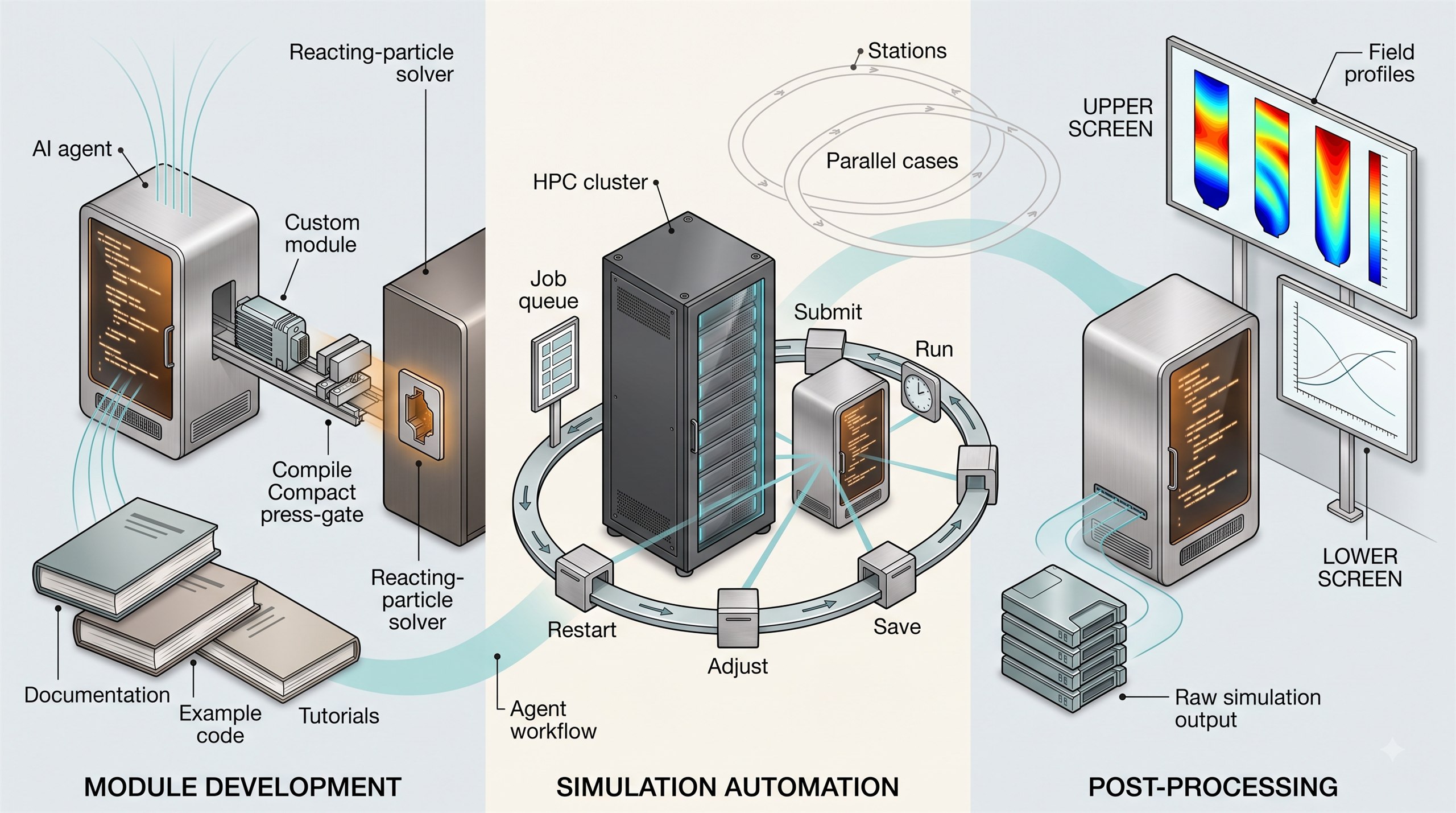
Writing it is skilled, slow work. So I trained an AI agent on the software's
developer documentation, along with example code and tutorials. It now writes and
compiles a working module on its own.
Where the agents do the work: writing the module, running the cases, and turning the output into results.
The second job was duller and cost more time. A simulation could only run about an
hour before it had to be stopped and saved, adjusted by hand in the interface,
written out as a restart file and started again — then the same thing an hour later,
for every case, each covering a full day of reactor time. Days of my week went on
that. An agent now runs the whole loop in Python: it submits the jobs, handles the
restarts and keeps going without me.
The third piece is AMReX, an open-source simulation framework the laboratory's SAMS
group has already built codes on. I trained an agent on those codes and set it to
work on iron ore reduction. It can reproduce a model of one ore pellet turning into
iron, which I had built in COMSOL during my PhD.
Reactor Modeling
Modeling Ironmaking on Pilot and Industrial Scale
Arizona State University · National Laboratory of the Rockies · 2020–present
95 %+ of the ore turned into metal, guided by the model
$15M pilot plant investment informed by the cost analysis
1st reactor in the USA to make iron with hydrogen, modelled and checked
Iron is made in a shaft furnace: pellets of ore go in at the top, hot reducing gas comes up
from below, and reduced iron leaves at the bottom. That gas has normally been made from
reformed natural gas.
In 2021 the United States Department of Energy started the Grid-Interactive
Steelmaking with Hydrogen project, or GISH, to lower the risk of investing in the
equipment needed to make iron with hydrogen instead and turn it into steel in an
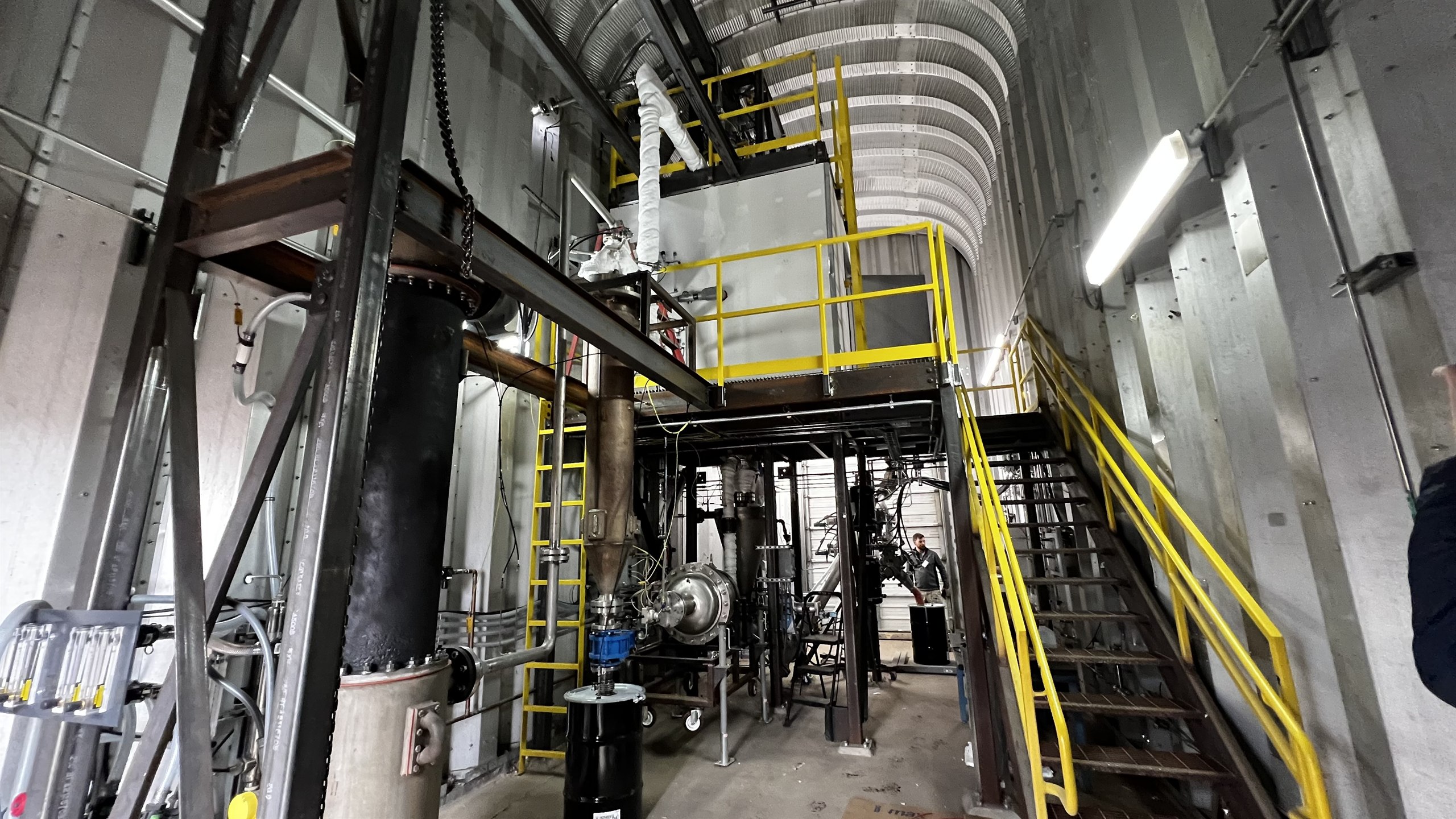
electric arc furnace. A pilot reactor was built as part of that project. It was
small, but built to the same design as a full plant so its results would carry over.
One of the things we wanted to know was how it would behave when the feed was changed
from pure hydrogen to a mixture of hydrogen and reformed natural gas.
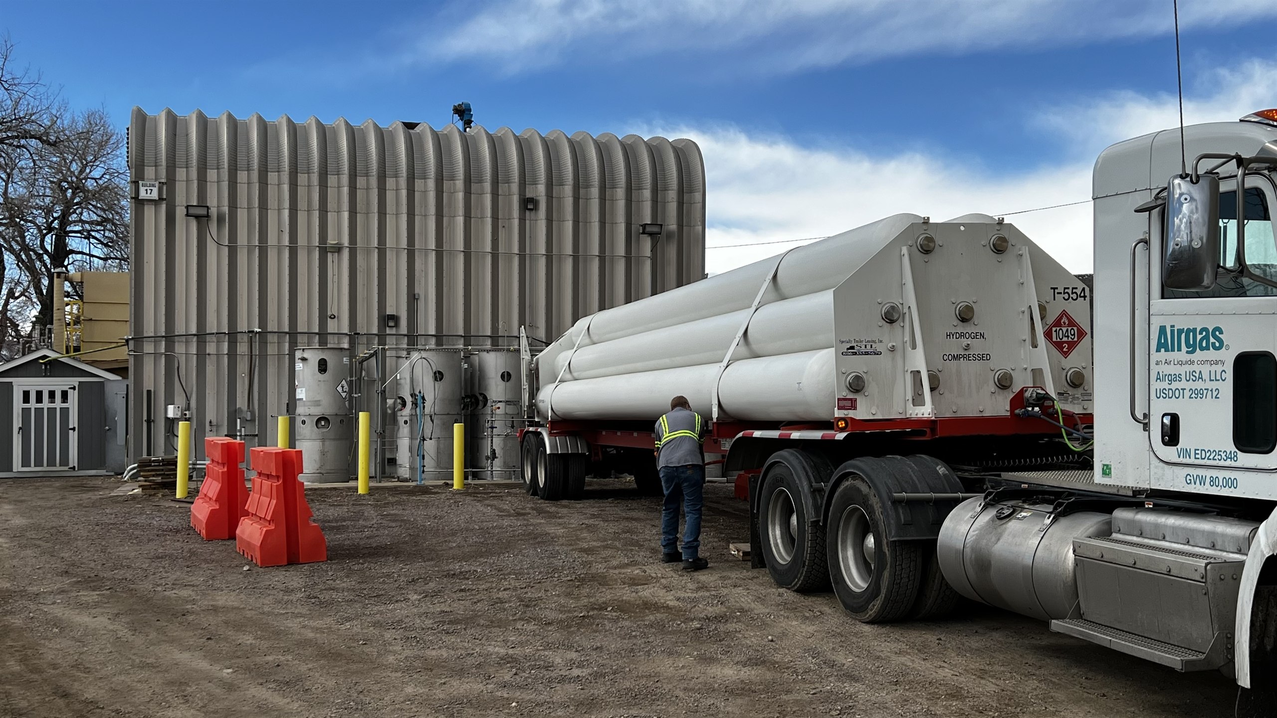
Inside the pilot plant.Hydrogen arriving at the site by tube trailer.
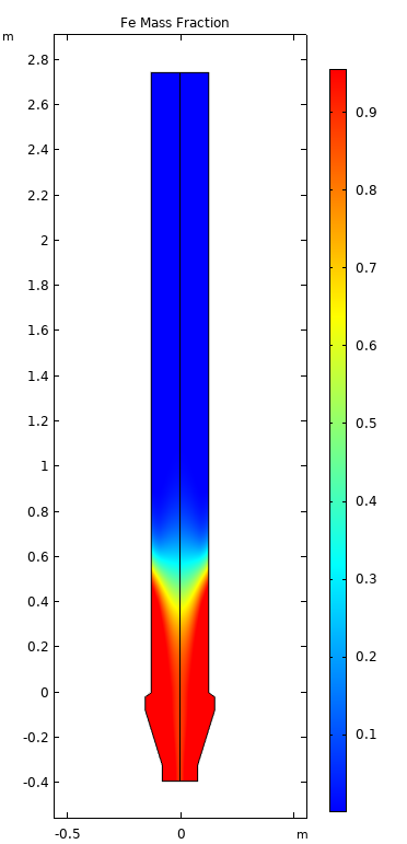
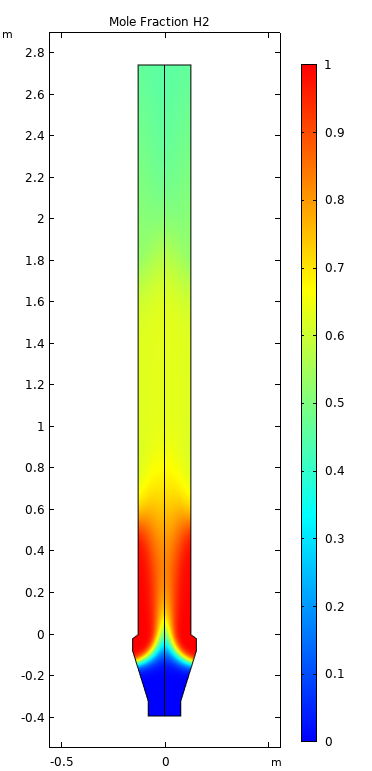
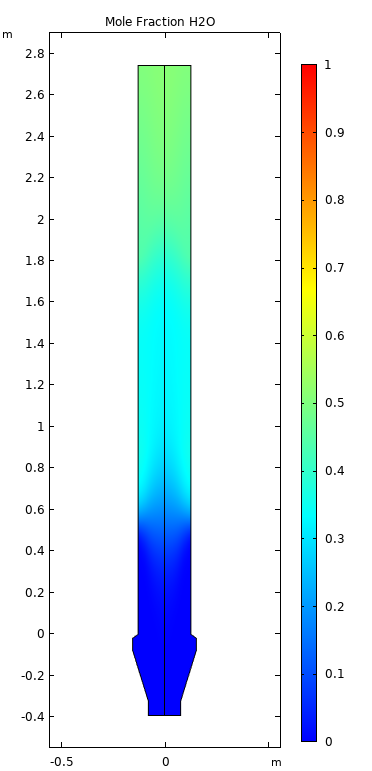
I built a FEA multiphysics model of that reactor. What it predicted for the quality of metal produced
was close to what the plant actually made, and so were the temperatures it gave for
the inside of the furnace. That agreement is what made it usable on the plant rather
than only on paper. When the pilot clogged during commissioning, the model was used
to work out how to bring it back into operation, and to say in advance how a startup
would go. The work is described in
this
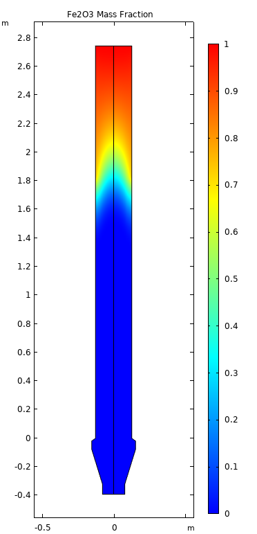
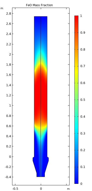
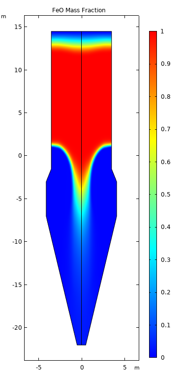
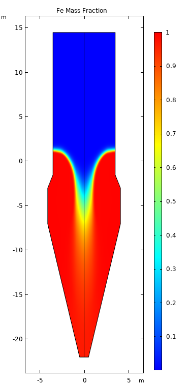
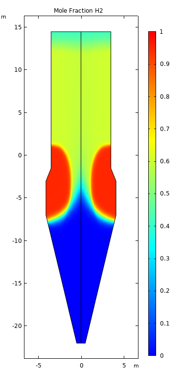
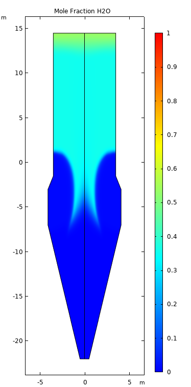
paper. The pictures below show the simulation results at a steady state, showing
how the soild species and gaseous species vary inside the pilot reactor geometry.
Iron ore, Fe2O3Part-reduced, FeOIron, FeHydrogen, H2Water vapour, H2O
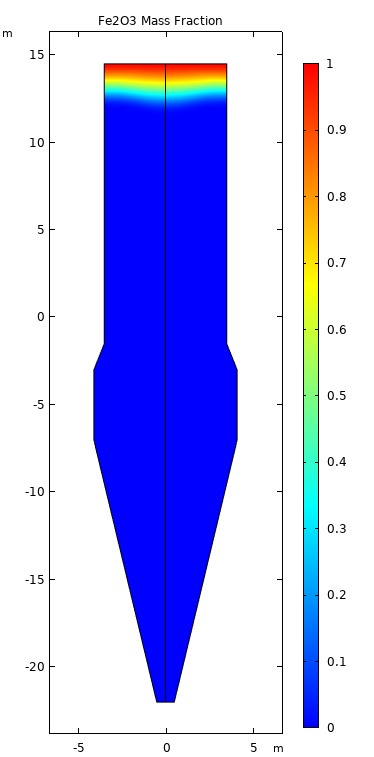
The same model was then scaled up to industrial size, to a shaft of the proportions a
commercial plant would actually use. No plant of that kind existed to compare it
against, so the scaled version rests on the agreement already established at pilot
scale. One result stands out on its own: the reactor needs appreciably more hydrogen
than the chemistry alone would require, and the surplus leaves unused. The pictures
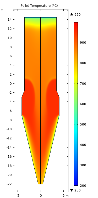
below are the same set of profiles for that larger reactor, with the temperature of
the pellets added.
Iron ore, Fe2O3Part-reduced, FeOIron, FeHydrogen, H2Water vapour, H2OPellet temperature
Chemical Kinetics
Simulating Iron Ore Reduction on Lab Scale
Arizona State University · 2020–2024
22 citations on the resulting paper
3 temperatures, from 800 to 900 °C
3 gas flow rates measured at each one
For as long as anyone has made steel, the job has been the same one: get the oxygen
out of the iron ore. What changes is the gas you use to do it. That gas has usually been
made from coal, natural gas, and commercial plants have decades of experience running on it. Then
hydrogen arrived as the alternative — and when someone asked how a furnace would
actually behave once it switched over, there was no confident answer.
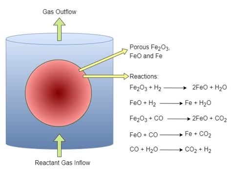
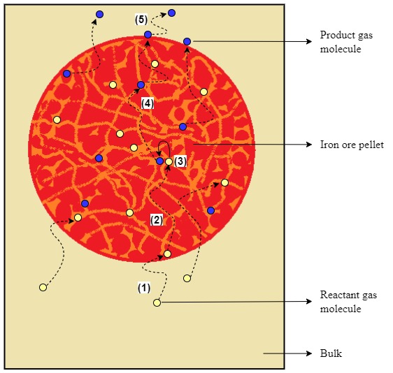
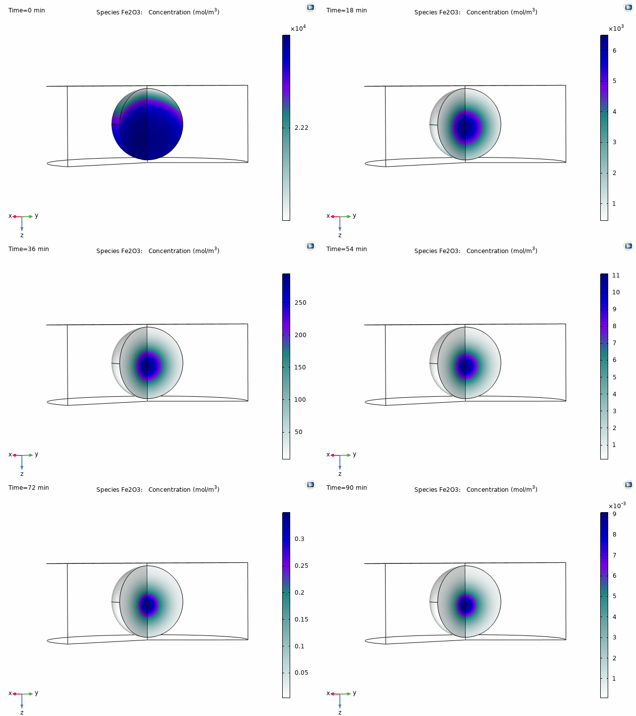
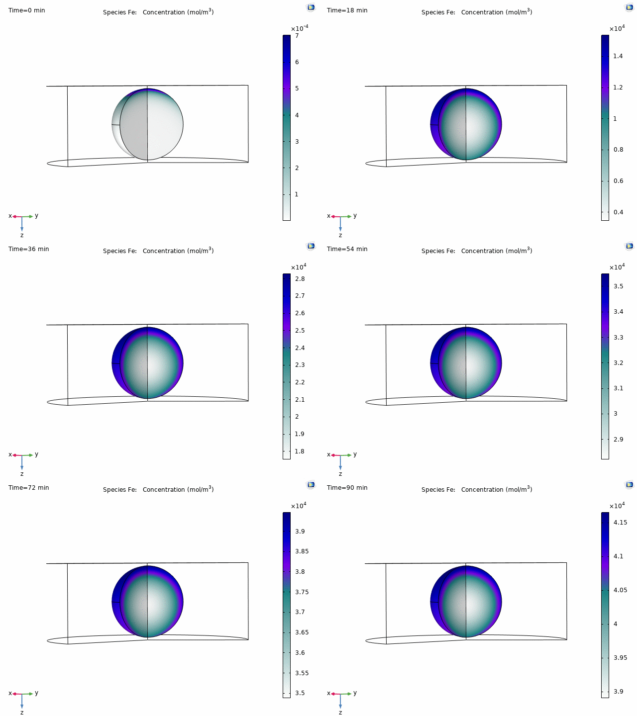
Iron ore reduction using hydrogen and carbon monoxide.Gas diffusion and reaction inside a pellet.
You cannot find the answer by watching. An industrial furnace is millions of pellets stacked
several storeys deep, sinking slowly through a reducing gas mixture, and nothing about the inside of
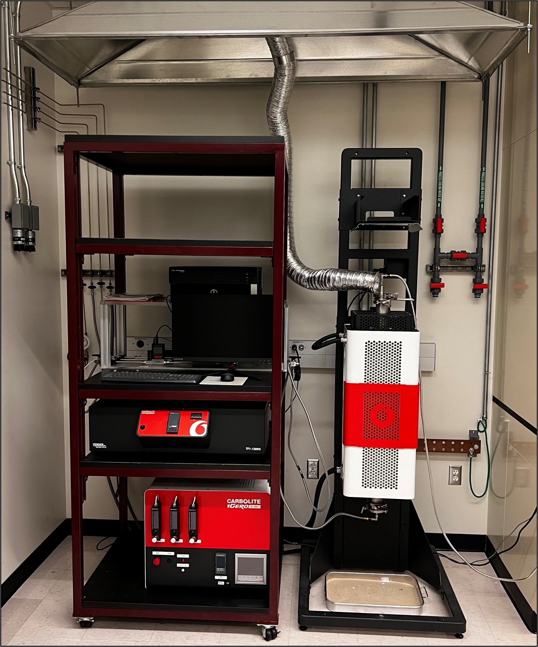
that pile is visible from outside it. So the question had to be made smaller. We took
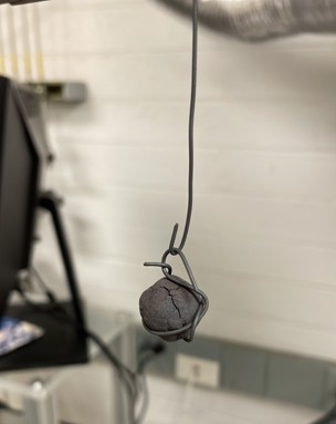
a single pellet, hung it on a wire, and lowered it into a furnace on its own — one
pellet at a time reduced using different gas mixtures, at different temperatures, followed from start to finish. How long did it
take to turn iron ore into iron, and what held it back? These experiments helped us obtain the chemical kinetics of the reduction process.
The lab furnace experimental setup for reducing pellets.A single pellet on its wire hanger, ready to go into the furnace.
Do that enough times and a pattern appears. The data obtained from the pattern goes into a model, and once
the model can reproduce what the pellet did on the laboratory scale, you can start asking it
about pellets nobody has tested — a different gas, a different mixture, a furnace
that has not been built yet. That is what the whole exercise is for. A question that
used to be settled by trial and error on a running plant gets answered on a computer
first. The measurements and the model are set out in
the
paper.
Fe2O3Simulation of a single pellet — the raw ore being used up.FeThe same run — iron metal appearing in its place.
Gas Separation
Membranes and Electrospun Fibers for Gas Separation
Arizona State University · IIT Bombay · Tata Centre · 2015–2021
84 citations on the resulting review paper
99+ different gases can be tested
50 % less time to test a membrane
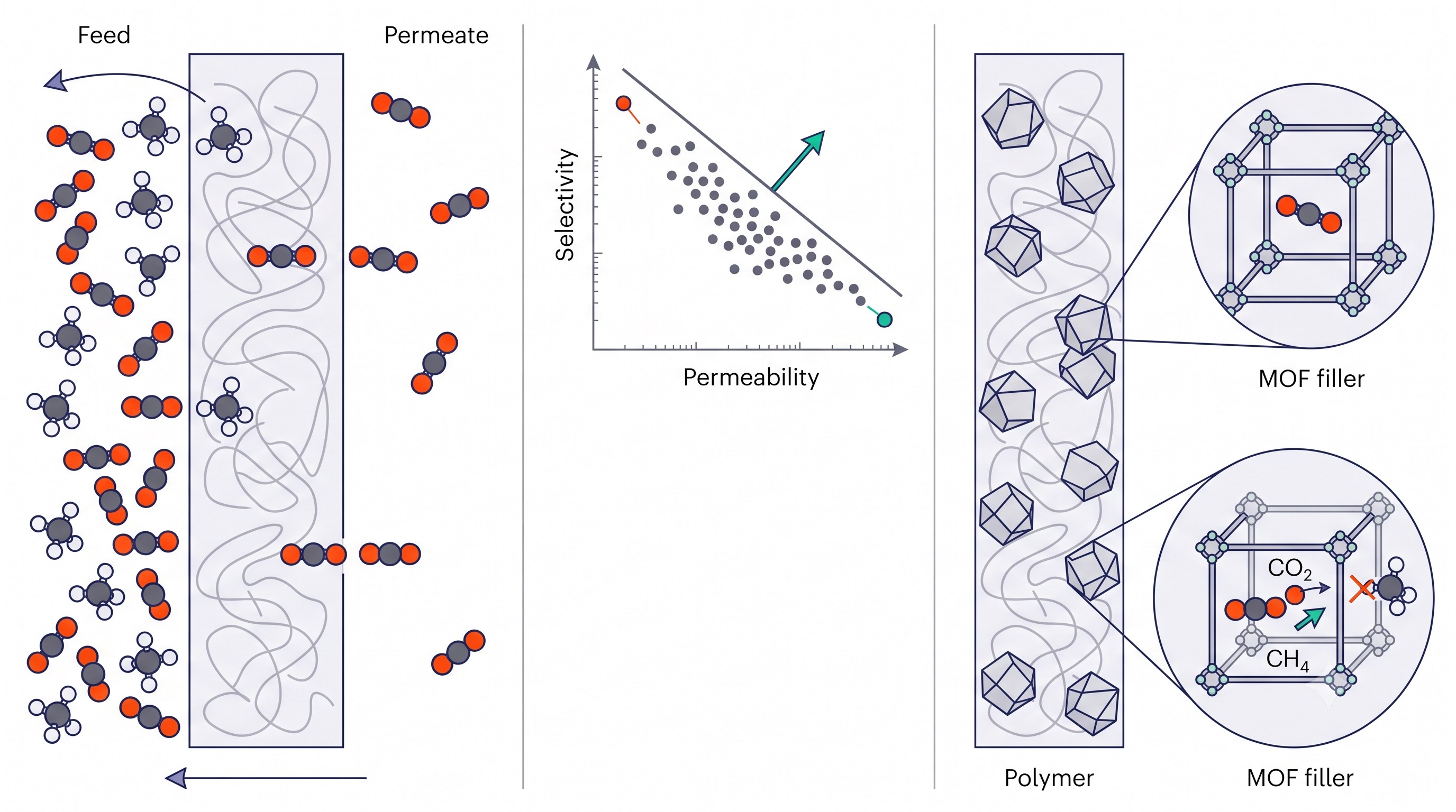
A membrane is a thin sheet of polymer that pulls one gas out of a mixture without
ever having to turn it into a liquid. All it needs is higher pressure on one side
than the other, and one gas slips through faster than the rest. The catch is a
stubborn one, and it is about the material rather than the machinery: the sheets
that are fussiest about which gas they let through are also the slowest, and the
quick ones are not fussy enough. You can have a clean separation or a fast one, but
not both — which is what has kept membranes out of the harder jobs. Mixing tiny
crystals into the polymer is one way around it. The most promising ones are called
metal–organic frameworks: they are riddled with holes of a very exact size, so
small molecules pass through and larger ones cannot, their structure can be tuned to
the job, and they sit comfortably in the polymer rather than fighting it. My
co-authors and I set that case out in
a
review of the field for the Journal of Polymer Science.
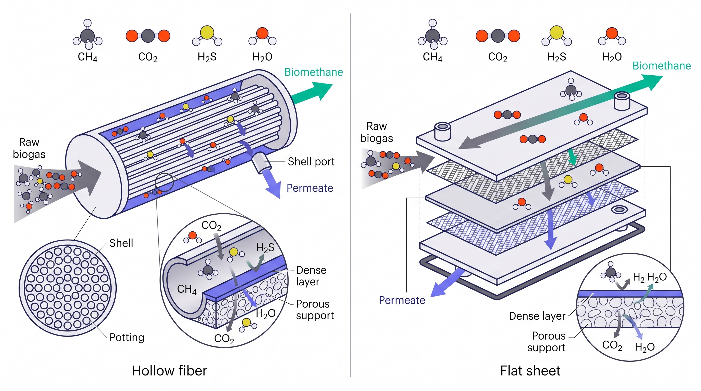
Two ways to package the same membrane. In both, the unwanted gases pass through it and are drawn off to the side; the methane never crosses it, and comes out of the far end.Left: gas works its way through a solid polymer sheet. Middle: the sheets that separate best are the slowest. Right: crystals mixed into the polymer are a way past that.
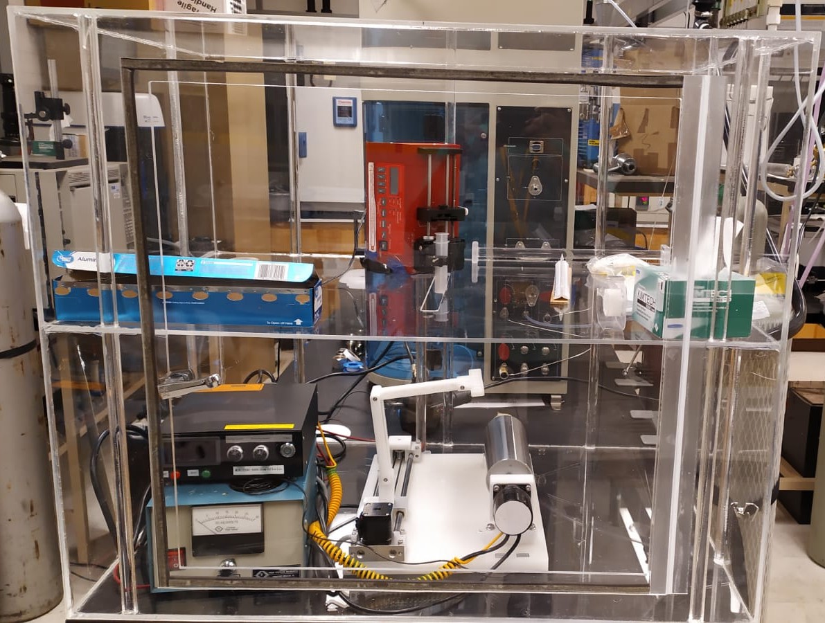
At Arizona State University I built a setup that makes electrospun fibers with those crystals inside fibers. It draws
a single thread out of two liquids at once, one wrapped around the other, so the
crystals and other tiny particles end up sealed inside the thread rather
than sitting on its surface. Fibers made this way separate a gas by a different
trick from the sheets: instead of letting one gas through, they catch it and hold on
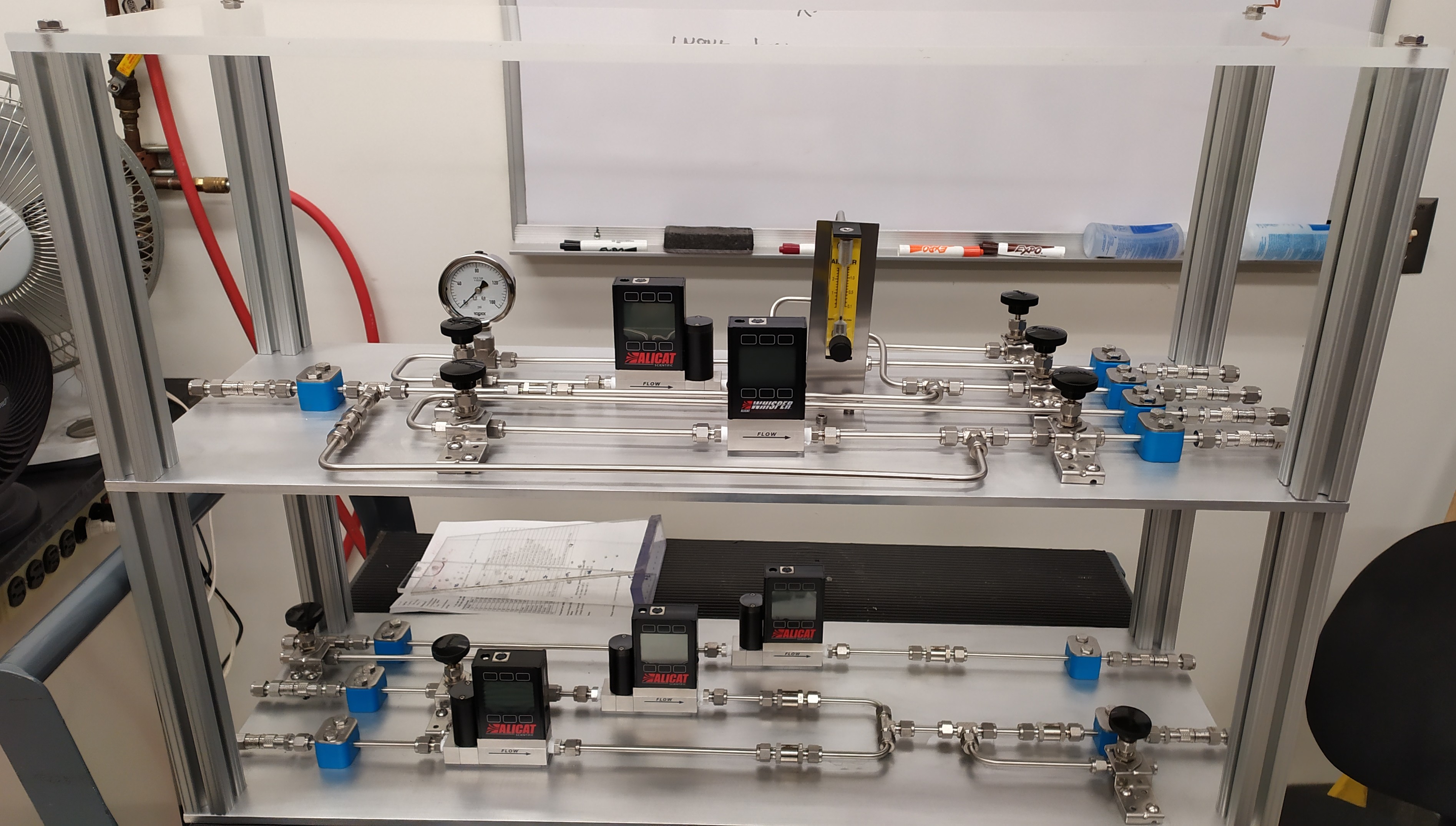
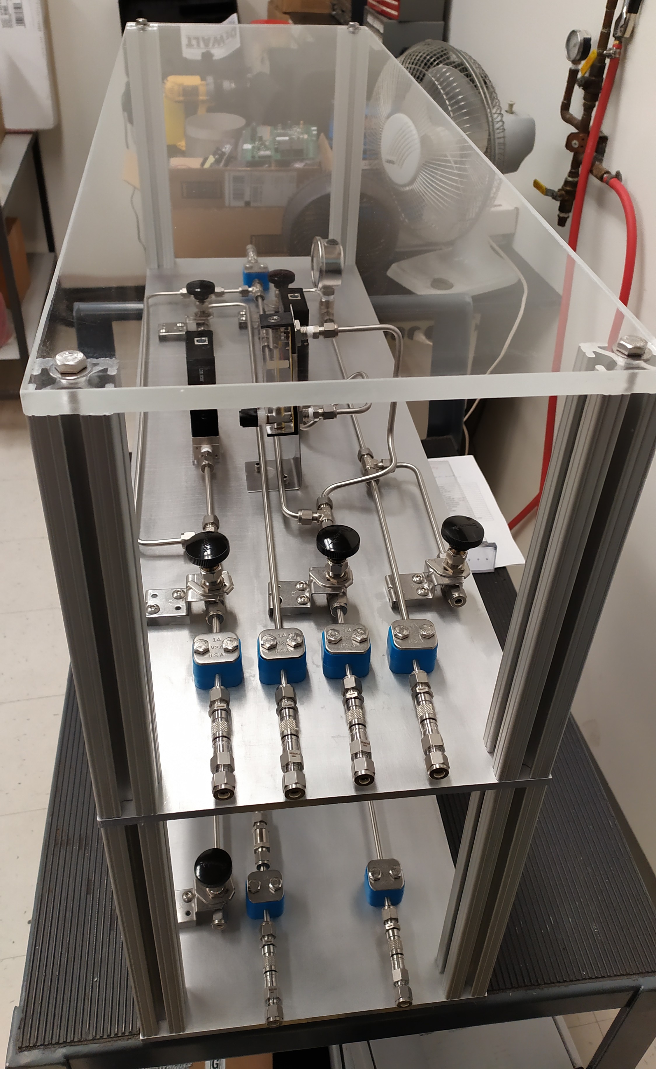
to it in the adsorption process at high pressure. The two approaches were running side by side. I also built the test rig that
measures how the sheets themselves perform, in both of the shapes they are made in —
flat sheets, and bundles of fine hollow tubes.
The fiber-spinning machine I built at ASU.The test rig I built at ASU, for measuring both flat sheets and bundles of hollow tubes.Close-up of the gas controls.
Earlier, at IIT Bombay and the Tata Centre, I built a test rig of my own. What drove
that work was biogas — the gas that comes off rotting organic waste such as cattle
dung. It burns, but it comes out watered down with carbon dioxide and other unwanted
gases. Take those away and what is left is concentrated methane, the same gas piped
into kitchens. I learned to make the hollow tubes there on the Membrane Lab's
existing equipment, under Prof. Jayesh Bellare.
Spin fabrication of hollow fiber membranes.The test rig I built at IIT Bombay.
Photos & Videos
Some conversations about the work — and a few milestones, podiums and posters.
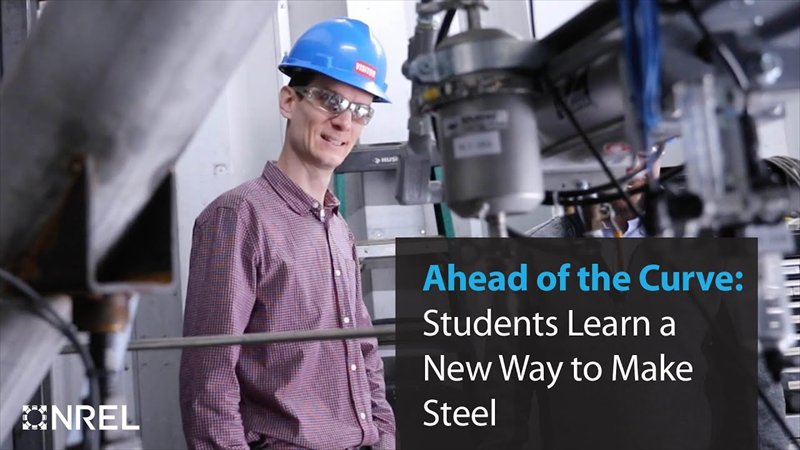
Ahead of the Curve: Students Learn a New Way to Make Steel
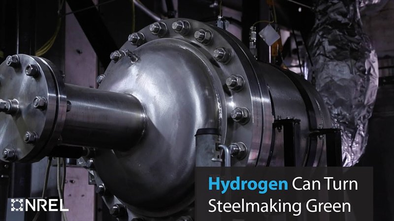
Hydrogen Can Turn Steelmaking Green
Interview — biogas in rural India, and the case for cleaning it up
Biogas in rural India — a digester construction at a village school
PhD convocation, 2024 — Arizona State University (With Prof. Sridhar Seetharaman)Presenting at AISTech, the Association for Iron & Steel Technology's annual conferenceDual degree convocation, 2017 — IIT Bombay (With Prof. Ravindra Gudi)Make in India Hackathon Poster, 2016 — hollow fibre membranes for cleaning up biogasResearch internship, 2014 — Aristotle University of Thessaloniki, on biomass pyrolysis (Prof. Anastasia Zabaniotou)
Experience
Postdoctoral Researcher — Computational Science Center
National Laboratory of the Rockies
Apr 2024 — Present · Golden, Colorado
Doctoral Researcher — School for Engineering of Matter, Transport and Energy
Arizona State University
Aug 2019 — Mar 2024 · Tempe, Arizona
Research Engineer
Tata Centre for Technology and Design
Feb 2018 — Jul 2019 · Mumbai, India
Research Intern
Aristotle University of Thessaloniki
May 2014 — Jul 2014 · Thessaloniki, Greece
Education
PhD, Chemical Engineering
Arizona State University
2019 — 2024 · Tempe, Arizona
BTech & MTech, Chemical Engineering
Indian Institute of Technology Bombay
2012 — 2017 · Mumbai, India
Speaking & Press
Conference Talks and Guest Lectures
MS&TOct 2024
Modeling Iron Ore Reduction on Pilot and Industrial Scale to Determine the Economic Penalty of Pure H2 Operation
J. Winarta, A. Meshram, F. Zhu, R. Li, H. Jafar, K. Parmar, J. Liu, B. Mu
84
Contact Me
If something here overlaps with what you are working on, I would be glad to hear about
it — whether that is a problem you are trying to model, a collaboration, a role
you are looking to fill, or an event you are putting together.





 Fluent
 AMReX
AMReX Python
 Agentic Modeling
 C++
C++